with Group Control, Size 1175×575×320mm")
 with Group Control, Size 1175×575×320mm")
 with Group Control, Size 1175×575×320mm")
Description
Intelligent Distributed Control System for FFU – Ideal for Large Cleanrooms
The FFU Intelligent Distributed Control System is specifically designed for large-scale cleanroom environments. It enables both decentralized on-site control and centralized unified management, offering flexible control over the startup, shutdown, and speed adjustment of FFU fans. By adopting a zoned control architecture, the system overcomes the limitations of RS485 driver capacity and can manage thousands of FFU units simultaneously.
The control system consists of three main components:
-
FFU Computer Management System (Monitoring System)
-
FFU Central Controller (Main Host System)
-
On-site FFU Control Units
1. FFU Computer Management System
This system uses specialized monitoring software with a main interface and sub-interfaces.
-
The main interface displays the distribution and zoning layout of the FFU system and allows for direct zone-based power control.
-
Clicking on any zone in the main interface leads to the sub-interface, where the status of each FFU in the zone can be viewed and individually controlled.
2. FFU Central Controller
The central controller is the core of the FFU group control system.
-
It features an LCD display and supports remote monitoring and adjustment of each FFU control unit.
-
It can transmit and receive signals to and from the computer.
-
Even if the computer is not connected or is turned off, the controller can independently manage and configure the entire system.
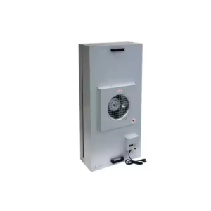
3. On-site FFU Control Units
Each control unit uses a microcontroller as the core processor to serve as the terminal controller for a single FFU.
One control module corresponds to one FFU unit.
The unit supports the following functions:
-
Start/stop and speed control of each FFU via the central controller
-
Remote centralized control and fault diagnostics
-
Configurable ID address for each unit
-
Overload and no-load alarm functions: alarms will trigger when abnormal load conditions are detected
Technical Specifications
-
Power Supply: 220VAC
-
Fan Type: Three-tap motor
-
Communication Method: RS485 (Refer to protocol appendix)
Operating Instructions
-
“ON/OFF” Button (Only effective under local control mode: ID = 00)
After wiring according to Diagram 2 and verifying safety, power on the system. Press this button to start the FFU; press again to stop. -
“Up” Button
Press this button during operation to increase fan speed. -
“Down” Button
Press this button during operation to reduce fan speed.