Description
FFU Intelligent Distributed Control System
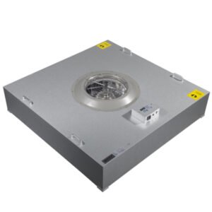
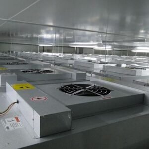
The FFU intelligent distributed control system is mainly designed for large-scale cleanrooms. It enables both convenient on-site distributed control and centralized unified management. The system allows flexible control of FFU fan start/stop functions and speed adjustment. By using zone-based control technology, it overcomes the limitations of RS485 driver capacity and can manage up to several thousand fan units.
The control system consists of the following three components:
-
FFU Computer Management System (Monitoring System)
-
FFU Control Host System
-
On-Site FFU Control Units
Computer Monitoring System
The computer is equipped with professional FFU monitoring software. The software includes a main interface and sub-interfaces:
-
The main interface displays the FFU system distribution map and zone diagram. It allows direct control of zone power (on/off).
-
By clicking a zone on the main interface, users can access the sub-interface, where they can monitor the status of each FFU and control each individual FFU control unit.
FFU Control Host System
The FFU main controller is the core of the centralized control system. It features an LCD display and allows remote monitoring and adjustment of FFUs. The host controller can set and manage each FFU control unit and send/receive signals to/from the computer.
Even if the system is not configured with a computer or the computer is powered off, the FFU control host can independently complete all system configuration and control tasks.
Note: Non-standard customization is available upon request.
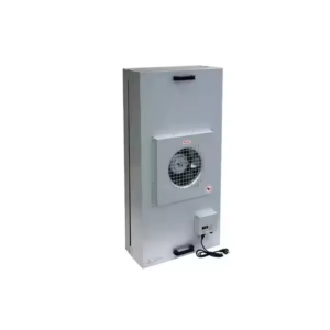
On-Site FFU Control Unit
Each FFU control unit uses a microcontroller as its core processor and serves as the terminal controller for a single FFU. Each unit module controls one FFU and supports the following functions:
-
Start/stop and speed control of each FFU via the host controller
-
Remote centralized control and fault diagnosis
-
Each unit has a configurable ID address
-
Overload and no-load alarm functions — the control unit issues an alert if overload or no-load conditions are detected
1. Main Technical Specifications
-
Power supply: 220V AC
-
Three-tap fan support
-
Communication interface: RS485 (communication protocol available in appendix)
2. Operation Instructions
-
Power On/Off Button (Only valid for local control when ID = 00)
-
Follow wiring diagram (Diagram 2) to ensure proper connections before powering on.
-
Press the button to power on; press again to power off.
-
-
Increase Speed Button
-
When the unit is running, press this button to increase fan speed.
-
-
Decrease Speed Button
-
When the fan is running, press this button to reduce fan speed.
-